Monday, May 11, 2015

Malcolm's New Family


Meet Malcolm, the unfortunate kitten. He has a scar on his belly due to a tragic incident that involved a red scooter and ice cream. It began on the day of the circus. Tommy was ecstatic to go to the circus, his mother less so, being a nervous wreck around crowds. Tommy just got a new grey cat named Malcolm who he spent every hour and minute of the day with, and he insisted on bringing his new kitten to the circus with him. If he didn’t, Tommy thought that Malcolm would get lonely at home. Tommy’s mother, being overly accommodating, agreed, much to her demise later. When Tommy and his mother arrived at the circus, Tommy headed straight for the dart balloon game with Malcolm in his chubby hands. This is where it got bad for Malcolm. Tommy put Malcolm down by the counter. Tommy was aiming for the giant teddy bear; his entire concentration was focused on the game. Tommy’s mother, being already a nervous wreck, was scared that Tommy might hurt himself with the darts. They both paid no attention to Malcolm. Malcolm, being the curious little cat he is, wandered off the counter and into the mass of people. Malcolm had already wandered much too far before Tommy or Tommy’s mother noticed. Malcolm’s solo adventure was tragically cut short. Much to Malcolm’s demise, a child riding a small red scooter, holding an ice cream cone, zoomed by, much too preoccupied with his ice cream to notice tiny Malcolm. The child ran straight into Malcolm. The collision was much like a slow motion film. Malcolm was knocked to the side, the child tripped slightly, and the ice cream cone slipped out of his hands, landing top first onto the concrete. The child burst out crying. The crowd rushed towards the child, ignoring poor Malcolm. Luckily, a little girl with a kitten in her arms noticed Malcolm. She tugged her mother towards Malcolm, and Malcolm was brought to animal ER, and sewn up just fine. He now has a new home, with a new cat and family.


Malcolm is a plush cat, outfitted with an arduino that takes readings from a force sensitive resistor and several hall sensors. He's been adopted by a loving family that already has a cat, who just so happens to have a collar decorated with magnets. He's so happy to have a loving family that whenever he gets cuddled by his new owner or feline friend (aka, when he's squeezed or when the cat comes up next to him) that he just can't stop purring!


The target audience is any cat owner, and does solve an existing need. It doesn't enhance an existing interaction, necessarily, but it can help an owner of a new skittish cat help their new pet relax and grow accustomed to their new home, so it can enhance an interaction between a human and their cat.

We bought a plush cat (10 dollars), a hall effect sensor (about 2 dollars), a set of magnets (about 10 dollars), and a collar as well (10 dollars).

Our team members are myself (Sarah Lerner) and Natalynn Chun. 
Natalynn is an econ major and compsci minor, and is very creative.
Sarah is a compsci major and linguistics minor, and is fairly resourceful.

Here are some work in progress photos:


- The arduino with one hall sensor and a speaker


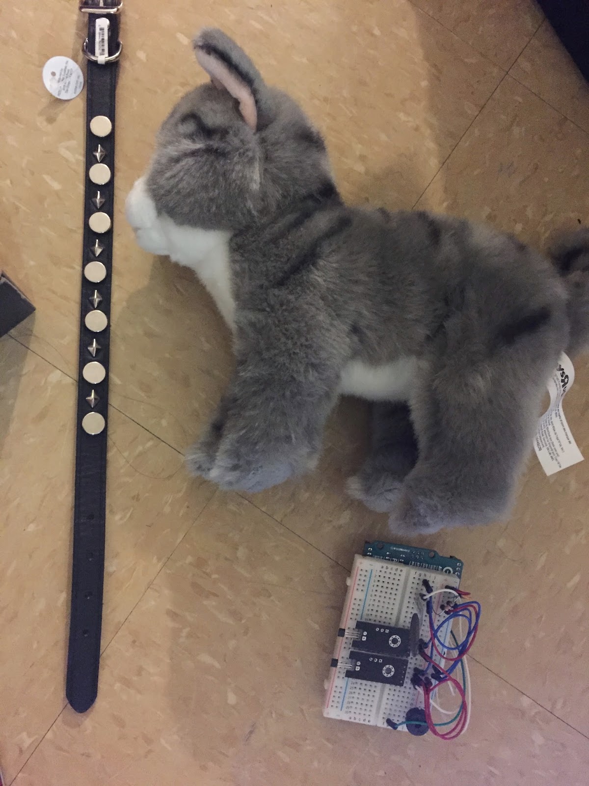
- Malcolm and the collar, along with the arduino, which now has two hall sensors and a force sensitive resistor.

Wednesday, April 22, 2015

Baby Mechatronic Dinosuar

For this assignment, Natalynn and I made a simple wireframe dinosaur who raises and lowers its head when a crank is turned. Our DC Toy Motor was not powerful enough to pull the crank on its own, but both parts of the project do work separately, as shown in the videos below.


Video 1: The motor is shown pulling the string taut, but without the force necessary to pull the crank.


Video 2: The crank is moved manually to show the dinosaur's head and tail moving.

Monday, April 13, 2015

Lab 7 - Motor Labs

1. Controlling a Servo Motor from Processing


2. Use the potentiometer to control the speed of a DC toy motor.


3. Control the speed of the toy motor with processing


Monday, March 30, 2015

Midterm Project

The title of your project: Coaster for Health

Sample Video (with each light set up to light up every second, for demonstration's sake):


Describe the concept:
During a stressful work day, people often forget to keep hydrated, going for hours at a time without a drink. In order to help people follow the 8 by 8 rule (8 glasses of 8 ounces of water a day) at a standard 9-5 desk job, we've created a coaster that will remind the user to drink water every fifteen minutes.

Describe the target audience:
The target audience is someone who works a desk job, either from home or in an office setting.

Describe the technical system:
After about a minute and a half have passed since putting a mug on the coaster, a light will come on. This continues until fifteen minutes have passed, and all the lights will blink on and off until the mug is picked up. The timer resets when the mug is placed back down.

Spec out what parts you will need, where you will get them from, and prepare a preliminary bill of materials, including cost for all parts.
Arduino (already purchased)
Plastic Box- $4
Lace Dollies- $4
Total Expected Cost: $8

What manufacturing techniques will you be using?
Cutting out paper, glueing and taping.

Document what possible problems you forsee (i.e. wrong choice of sensors for the job, or problems getting overly-complicated output devices to work), and document some back up contingency planning for those scenarios.
– The photoresistor may not be able to sense an empty bottle of water (hence the need for a mug instead of a plastic bottle)
– The user will be forced to refill their mug constantly while using the coaster and might simply ignore it after a while (the entire point is for them to drink from and refill their mug though - perhaps using a tumbler and not a mug would make more sense)

Document how your team will work together, and the division of labor for the next steps
Our group members are Sarah Lerner and Natalynn Chun. We will divide the labor equally.

Progress Photos:


Monday, March 23, 2015

Lab 5 - Processing Labs

1. Oscillating Circle with Processing


  • Processing is based on Java.
  • A global variable is able to be referenced at any point in a program, whereas a local variable can only be referenced within the function in which it was declared (and will consequently disappear when the function ends)
  • The draw() function returns a void data type.
  • The code below the "//keep the circle in bounds" comment checks to see if the circle has gone to or past the top or bottom of the window. The variable y refers to the center of the circle, so y - (diameter/2) is the y-coordinate for the top of the circle, and y + (diameter/2) is the y-coordinate for the bottom of the circle, so when the top of the circle hits the top of the window (at y-coordinate zero) or when the bottom of the circle hits the bottom of the window (at y-coordinate "height"), the y-speed reverses.
2. Sending Serial Data from an Arduino Circuit to a Processing Application


3. Etch-A-Sketch


This circuit uses a potentiomenter and a photoresistor to create a 'sketch' through Processing.

Tuesday, March 10, 2015

Assignment 2: Interactive Toy


The objective of the game is to throw or shoot something at the calendar, and hit Link square in the face three times. If you hit him again after that, a short jingle will play, and the game automatically restarts. Here, I am using it more as a punching bag, but ideally it'd be shot with a nerf gun or hit with a hacky sack, or something of the like.

The code for the song at the end was taken from a piece of the code from this webpage. The code for the actual game, as well as modifications to the above code, however, were made by myself, in addition to the actual design and set-up of the game seen above.

The intended user for this game is probably children from ages 6-12. Their attention span is still very limited, which is why the game only requires three hits before game is won, so they can play a couple times and then let it be for a while. The 'hit box' for the fsr is quite small, and requires a great deal of precision in order for something to actually register as a hit, so ideally, the child would use this as a means of target practice using a toy gun or simply tossing a small object, which would help to improve their gross motor skills (depending on how they choose to play) and their hand-eye coordination.

The user is allowed one affordance, which is to hit Link right in the face (behind which lies an fsr).

I don't know any kids to test this with, but I myself spend quite a while playing through it, though the design currently lacks a strong support system in the back (the giant stack of books in the video), and so the calendar continually loses the support in the back, which prevents the fsr from getting an accurate reading, so the great majority of the games I played were ended prematurely so that I could rearrange the books as necessary. I'd also like to increase the prerequisite number of hits to ten, and also add another fsr (a much larger one) behind Link's shield, so that any time the fsr reads above a certain value, the number of hits actually goes down.

Monday, March 9, 2015

Lab 4 - Servo Motors

1. Servo Motor Controlled by Pulse Width Modulation from an Arduino


  1. We add a delay after rotating the servo so it actually has time to rotate before running through the loop again.
  2. Pulse widths range from 544 to 2400 μs, for angles from 0 to 180 degrees, so 45 degrees = (45/180)(2400-544) + 544 = 1008 μs.
  3. The piezo speaker and the servo motor both use PWM from the arduino, which is not capable of reliably sending out both signals without any interference.
2. Servo Motor Controlled by Potentiometer with Arduino


3. Servo Motor Controlled by a Pushbutton Momentary Switch


Monday, March 2, 2015

Lab 3 - Introduction to Transistors

1. Force-sensitive resistor and LED with Arduino


  1. FSR's could be used in mobility devices (walkers, wheelchairs, and the like) to detect signs of distress in their users - while it would work best when combined with a temperature sensor, a very sensitive FSR could be used to detect heart rates, which, when elevated, could prompt, say, a message to be sent to their phone, informing them that their heart rate is dangerously elevated, and perhaps giving them an option to call paramedics or family, if they need to. Additionally, an FSR could be used in automated lifts, detecting when someone has stepped onto the lift and moving up or down accordingly.


2. Temperature Sensor and LED Circuit with Arduino


  1. The temperature sensor is not a variable resistor, and as such does not require the voltage divider circuit.
  2. Interactive designs based on this sensor would need to generate effects that are slow and gradual as well, instead of quick and immediate responses.
  3. Temperature sensors work well in Air Conditioning systems, reading the ambient temperature of a room, being fed in a desired temperature by the user, and heating or cooling the room depending on how the temperatures differ. This could also be used in a freezer (in a home, commercial, or laboratory setting) and alerting a specified user (or set of user) if temperatures fall above or below a specified range of values (this would be particularly useful for wine cellars, but could be useful in storing any temperature-sensitive objects).
3. Transistor as Amplifier


  1. Current always flows through the past of least resistance, and the path through the 560 Ohm resistor provides a lot less resistance than the path running through both the switch and the 10 k-Ohm resistor, so the LED turned on by the transistor will be brighter than the one turned on by the switch.
  2.  Give the approximate current flowing through each leg of the circuit (ignore any affect the transistor might have on the current flow or voltage drop).
    1. I = V/R ; I = (5V)/(560 Ohms) = 8.9 mA.
    2. I = V/R ; I = (5V)/(10 kOhms) = 0.5 mA.
4. Transistor as Switch


  1. When the potentiometer is offering its maximum resistance, there is very little current that can flow to the photoresistor, so its sensitivity will be dulled, whereas when the potentiometer is offering its minimum resistance, there is a lot of current flowing to the photoresistor, and as such its sensitivity will be much greater.
5. Transistor Controlled by Arduino


Wednesday, February 18, 2015

Lab 2 - Introduction to Microcontrollers

Part 1: Blinking LED with Arduino


Part 2: Reading a Switch with Arduino to Control an LED


  1. Keep the LED set-up the same, but rearrange the setup of the switch, so that the switch, when off, blocks the current from going directly to ground and instead redirects the current into pin2 (and therefore lighting up the LED), and when switched on, allows the current to flow directly into the ground, which would not light up the LED.
Part 3: Reading a Potentiometer with Arduino to Control an LED


  1. 5V
  2. 0V
  3. It must offer half of its possible resistance, which in this case is 5 k-Ohms.
  4. The LED's output values only go up to 255, but the potentiometer, being read via analogRead, goes up to 1023. Multiplying potVal by 0.25 converts the input values to a number that can be fed to the LED safely.
Part 4: Reading a Potentiometer with Arduino to Control a Speaker


  1. No, because the speaker has its own resistant properties, and drops some the current running through it.
  2. You would have to use smaller resistors, to allow more current to flow into the speaker.
  3. Are we having fun yet? Yes!!
Part 5: Reading a Photoresistor with Arduino to Control a Speaker


  1. Reverse the positions of the photoresistor and the 10 k-Ohm resistor. The less light shines on the photoresistor, the greater its resistance, and therefore the more current that will flow into the Pin instead of the ground, with the opposite effect when the light is greater.
MUSICAL INSTRUMENT!!!


Crawford's model of interaction describes interaction as a communicative process between two parties, in which both parties alternatively listen, think, and speak to one another. In this case, the parties are myself and my pseudo-instrument. I listen to the note being played, have to think about which note to play next and where to press in order to create it, and speak by hitting the next "key" with the knife. The instrument listens to which note is being pressed, thinks through the Arduino in order to determine the tone that should be played, and speaks by playing that tone.

My design is very shoddy (though it has since been 'clothed' in an old box of almonds, to mask the breadboard and Arduino), and is very very simplistic, in that it really only consists of a lot of 'switches' that need to be pressed in order to create a sound. The materials used could use to be improved (particularly my keys and the scotch tape i use to attach them to my wires) as well. It would be interesting to add in a potentiometer that could determine which key the notes are in (as of now they are all locked into major C), or somehow adding in a pressure-reader that would dampen the sound or not depending on how hard it's being pressed, to make the sound more dynamic, both of which would add interactivity to my design. In terms of expressiveness, adding in speakers to allow for chords would be a huge bonus, though it would require a redesign of my keys as well, or adding in LEDs that light up in designated patterns depending on the note being played, would help make my instrument more visually appealing.

Wednesday, February 11, 2015

Lab: Feb 4 2015

Part 1: Simple LED Circuit


  1. The purpose of the resistor is to weaken the current running through the circuit, preventing the LED (or anything else) from burning out.
  2. Since V = 5V and R = 560 Ohms, then I = 5/560, or 8.9 mA.
  3. If V = 5 and I = 15mA, then R = 5/0.015 =  330 Ohms
  4. 5 - 2.2 = 2.8 V
Part 2: Simple LED Circuit with Switch


  1. The circuit's behavior would not change. It'd just have the resistor dampen the current before it gets to the switch.
  2. The circuit's behavior still would not change.

Part 3: Simple LED Circuit with Potentiometer


  1. The resistor is necessary because without it, if the potentiometer was at its lowest setting (allowing the most current to pass through), the LED would burn out.
  2. V=IR ; V = 5 and R = (10,000 + 560), so I = 5/10560 = 0.047 mA.
  3. Rheostat, Thermistor, Humistor, and Photoresistor.

Part 4: Dueling LED's Circuit with Potentiometer


  1. When the potentiometer is turned, it increases the amount of current going through one LED (and therefore brightening it), and decreases the amount of current going through the other LED, dimming it.
Part 5: Capacitor Charging Circuit


  1. The capacitor will charge more slowly than before, since there will be less current flowing into it and charging it. As a result, the LED will stay lit longer.
Part 6: Capacitor Discharging Circuit with LED Delay


  1. The capacitor discharges up through the LED part of the circuit because that's where the positive charge is held, so in order to discharge, the capacitor has to go from the positive side (facing the LED part of the circuit) and travel through that section of the circuit in order to reach the ground.